
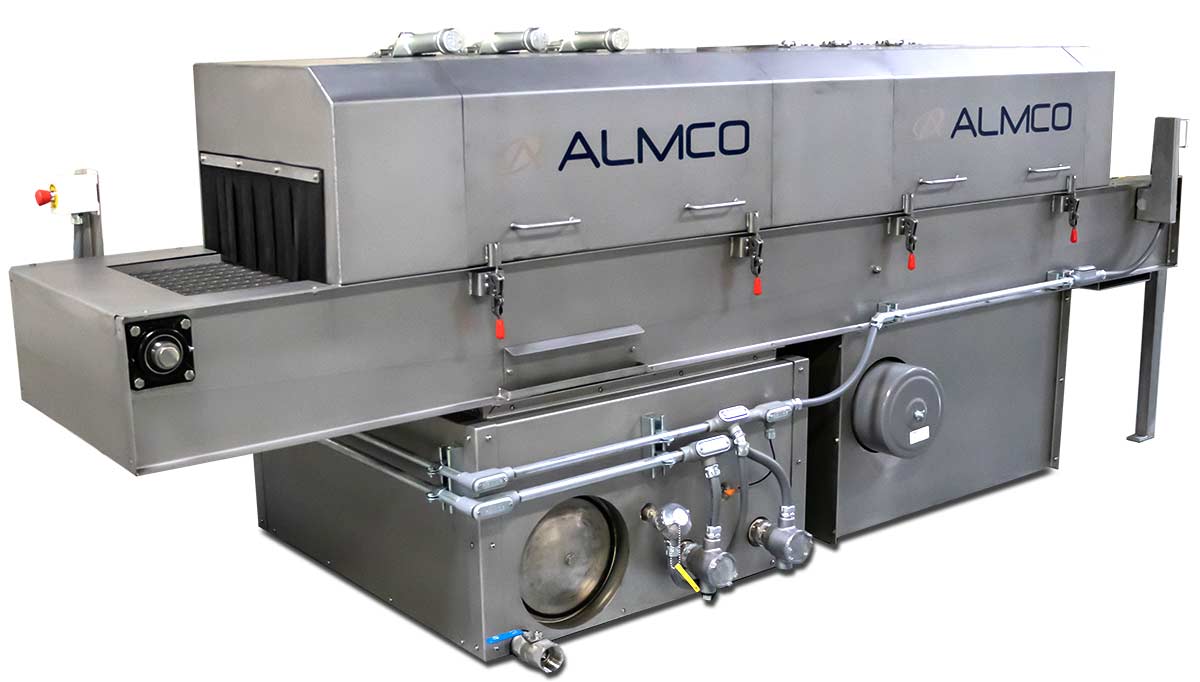
The PWRB24-48E is the largest standard model in the PWRB family, providing increased conveyor width for larger components and higher production volumes. Designed for demanding manufacturing environments, it delivers high-capacity automated cleaning while maintaining consistent wash quality and efficient blow-off performance.
Part Washing Equipment
PWRB24-48E Inline Conveyor Parts Washer
OVERVIEW
PWRB18-48E System Overview
The PWRB24-48E is engineered for manufacturers requiring greater processing capacity and increased throughput. Featuring a 24-inch conveyor belt and a 48-inch blow-off section, the system accommodates larger parts and higher production volumes while maintaining the reliability and process consistency of the PWRB platform.
Like all PWRB models, the system utilizes a water-based spray wash process followed by integrated blow-off technology to remove contaminants and residual cleaning solution. The larger conveyor width allows manufacturers to process wider components or increase throughput by running multiple parts simultaneously.
The PWRB24-48E can be configured with additional process stages, filtration systems, heated wash solutions, oil-removal equipment, and custom automation features to meet specific production and cleanliness requirements.
KEY ADVANTAGES
- Largest conveyor width in the PWRB family
- Increased throughput and part capacity
- Ideal for automated production environments
- Customizable to meet demanding cleanliness standards
COMMON APPLICATIONS
- Automotive and transportation components
- Large machined parts
- Stampings and fabricated components
- High-volume production cleaning operations
TECHNICAL SPECIFICATIONS
| Spec | Value |
|---|---|
| Overall Machine Dimensions (Approximate) | 12′-6″ Long x 68″ Wide x 52″ High |
| Process Stages | Wash: 48″ Drain Area: 18″ Blow-Off: 48″ Unload Station: 18″ |
| Conveyor Belt Height | 36″ |
| Work Opening Size | 18″ Wide x 9″ High |
| Conveyor Motor | 15 HP TEFC, 1750 RPM |
| Solution Tank Capacity | 290 gallons |
| Wash Pump | Gusher brand vertical end-suction centrifugal unit |
| Pump Motor | 5 HP, 3450 RPM |
| Flowrate | 72 GPM @ 40 PSI |
| Power Requirement | 460v (Others Available) 3 Phase, 60 Cycle |
| Drive Unit | AC Variable Frequency |
| Blow-Off Unit | 10 HP Gast brand regenerative blower |
| Blow-Off Rate | 250 CFM @ 100″ WC static pressure |
| Operator Controls | 110 volts supplied by a transformer within the control box |
| Electrical Controls | Conformance to N.E.C. electrical specifications |
| Electrical Enclosure | NEMA Type 12 panel enclosure mounted on the machine |
| Paint | Two coats of Diamond Vogel brand industrial enamel in Lunar White with Midnight Blue accent |
SYSTEM DETAILS
- CONVEYOR FRAME
- Conveyor Belt
- Conveyor Drive
- Solution Tank
- Wash Pump
- Electrical Controls
- Spray System
- Shroud Hoods
- Blow-Off
Conveyor Frame
CONVEYOR FRAME
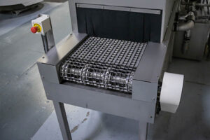
The conveyor system consists of one conveyor frame sections, one continuous conveyor belt and a drive unit.
The conveyor frame is mounted on top of the wash tank, and this frame/tank assembly provides the basic structure of the Load, Wash, Blow-Off and Unload Stations. The frame measures 32″ wide (inside) by 150″ long and is fabricated from 10-gauge 304 stainless steel sheets and structural reinforcing members using all-welded construction to provide a water-tight, first-rate appearance.
Conveyor Belt
Conveyor Belt
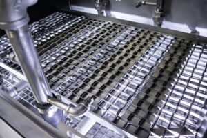
The conveyor belt is a Keystone brand 18″ wide flat-wire model with 1″ x 1″ openings and welded “button head” edges. The belt is fabricated from 304 stainless steel.
Flange-mounted bearings located on each outboard end of the conveyor frame support the conveyor’s 1-1/2″ diameter stainless steel drive and driven shafts. Each shaft holds sprockets that are specifically designed to fit the openings of the conveyor belt, providing positive belt drive and excellent belt tracking.
Conveyor Drive
Conveyor Drive
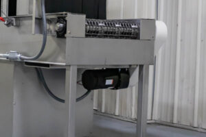
The conveyor is driven by a 1/4 HP 90 Volt DC gearmotor mounted beneath the discharge end of the machine. The gearmotor transfers power through roller chain and sprockets to a friction-type torque limiter mounted on the conveyor’s drive shaft.
Solution Tank
Solution Tank
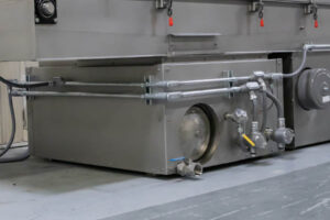
The solution tank of the Washer has a capacity of 290 gallons and is fabricated from 10-gauge 304 stainless steel sheets and structural reinforcing members using all-welded construction. The tank is located beneath the machine’s conveyor frame section, and along with the conveyor frame forms the main structure of the Washer. Floor pads on the underside of the tank allow the entire section of the machine to be picked up and moved via forklift during installation. In addition, the tank is approximately 16″ wider than the conveyor frame along one side of the machine, providing open tank area for mounting the top-pull-out wash pump. A tank drain fitting and a 12″ diameter stainless steel clean-out door are also provided.
Wash Pump
Wash Pump
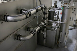
The wash pump is a Gusher brand vertical end-suction centrifugal unit with cast iron housing, and impeller, complete with a 3 HP, 3450 RPM motor. The pump delivers solution to the spray system which is sized to flow up to 72 GPM @ 40 PSI. A pressure gauge and ball valve are provided to monitor and control pump output.
PWRB Electrical
Electrical Controls
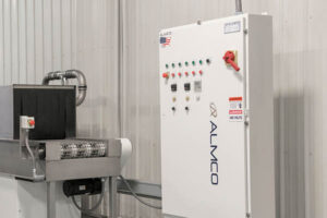
Electrical controls are housed in a free-standing NEMA 12 enclosure. All components within the enclosure are finger-safe and are Allen-Bradley brand unless noted otherwise. Components include a main disconnect switch, power distribution block, fuse holders and branch circuit fuses, Taylor wireways, terminal strips, a power supply to provide a 24 Volt DC control circuit, master control relay, a G.E. (or equal) transformer to provide 115 Volt single phase power (as needed), a PowerFlex variable frequency drive, and motor circuit protectors with thermal overloads and short circuit protection.
Equipment Power On and Emergency Stop pushbuttons are located on the front and/or side of the machine electrical enclosure. The optional touch screen includes all machine controls and is used to display system messages and to enter values for processing parameters.
All electrical components are UL listed and the machine is wired in accordance with NEC (NFPA 70) and NFPA 79 standards, ready for connection to your electrical service.
Spray System
Spray System
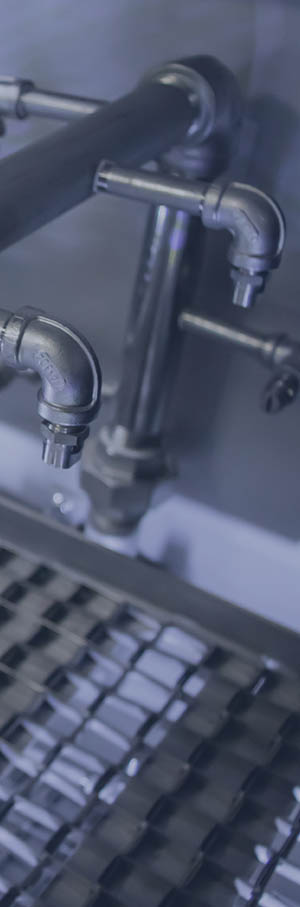
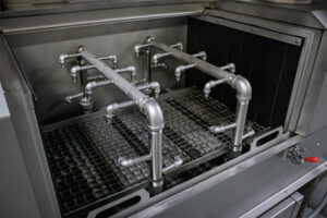
The Washer’s spray system consists of three stainless steel header pipe assemblies connected to a distribution manifold mounted on the inside of the conveyor frame. Each header assembly is made up of four 1″ pipes fit together with the manifold to encompass the conveyor belt providing top and bottom spray.
The individual 1″ pipes that make up the spray system have tapped holes to accept 1/4″ NPT stainless steel nipples and elbows for spray nozzle mounting, and standard nozzles are Spraying Systems brand “Flat-V” type made of stainless steel.
Shroud Hoods
Shroud and Hoods
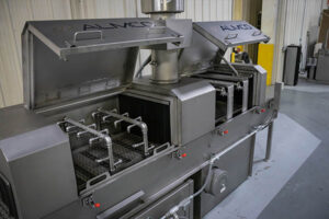
The wash spray system is shrouded by a 48″ long hinged hood that bolts to the open top of the conveyor frame. The open ends of the hood include neoprene rubber curtains that allow parts to pass through on the conveyor while effectively containing spray. Fabricated from 14-gauge 304 stainless steel, the spring-loaded hood is designed to swing open for easy access to the spray system.
Blow-Off
Blow-Off System
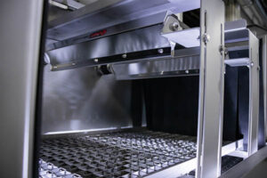
Designed to remove standing moisture from the product before exit from the machine, the Blow-Off consists of a hood weldment, a regenerative blower, air nozzles, piping, and controls.
The 48″ long Blow-Off hood is fabricated from 14-gauge 304 stainless steel and includes neoprene rubber curtains mounted on each end. The hood mounts to the top of the machine’s conveyor frame, just before the Unload Station.
Air is blown onto the parts through multiple 3/16″ diameter holes drilled into two stainless steel header pipes located above the conveyor belt and one stainless steel header pipes located below the conveyor belt. Air jetting from these holes acts to strip standing liquid from the parts.
The Blow-Off is powered by a 10 HP Gast brand regenerative blower rated to deliver air at 250 CFM @ 100″ WC static pressure. The blower mounts to the underside of the conveyor frame and is connected to the air nozzles by stainless steel piping. Bronze ball valves in the blower outlet piping allow airflow adjustments to the header pipes, and the blower includes inlet air filters and built-in mufflers for noise reduction. For additional noise reduction the blower mounting area under the conveyor frame is enclosed within a 14-gauge stainless steel shroud lined with 3″ thick sound-absorbing foam insulation.
FREQUENTLY ASKED QUESTIONS
How do I get the machine to my facility?
ALMCO can help arrange a truck shipment to get the machine to your facility. You may need to work with a local machine rigging company to place the machine properly in your facility.
How do I get the machine installed and set up to run at my facility?
After the purchase of a machine, ALMCO will provide installation, unloading and set-up instructions. You can also pay to have an ALMCO representative on site during the installation to ensure the machine is running properly and your operators are trained on using the system.
Do I need to purchase special cleaning chemical compounds to run in the system?
ALMCO carries a line of chemicals including cleaning compounds and rust inhibitors that are sold separately. It is highly recommended that you send in sample parts for testing prior to issuing a purchase order to ensure we find the right cleaning solution for your parts depending on the material and the dirtiness of the parts.
Do I need parts baskets, fixtures, racks or any other accessories to hold my parts?
In some cases parts are too small to stay on the conveyor on their own. ALMCO can help make recommendations for fixtures or baskets used in other customer applications.
What are other facility considerations needed to run this equipment?
You may need an exhaust fan, stack, ducting or a roof opening to allow mist to make its way out of the building where the unit is running. ALMCO offers mist and vapor collectors that integrate into the system and are sold as optional equipment.
How are the tanks cleaned out?
ALMCO provides threaded fittings on the rinse and collection tanks. These are ready for drain valves or piping from tank drain fittings to your wastewater collection system. There is also access doors on the tanks to allow for cleanout.
What if I need a different size machine to accommodate my parts?
If one of ALMCOs stock size units don’t work for your application, our engineers can put together a custom solution built specifically to your requirements. The cost and lead time are also increased with custom modifications.
OPTIONS & UPGRADES
Vapor and Mist Collection
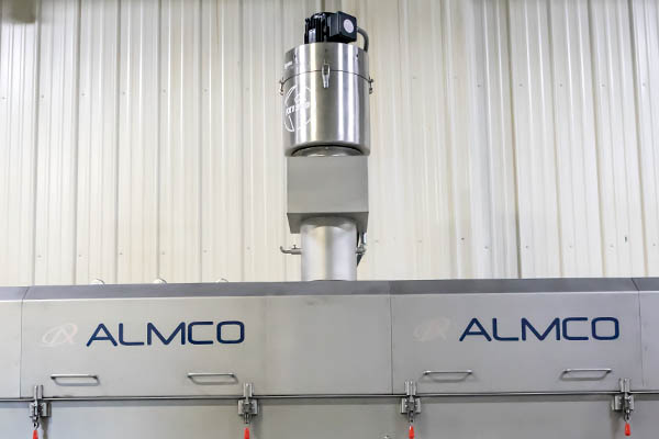
ALMCO will recommend the right system to collect the vapor or mist generated by the cleaning process to ensure the humidity level of your facility is not affected by running the washing system.
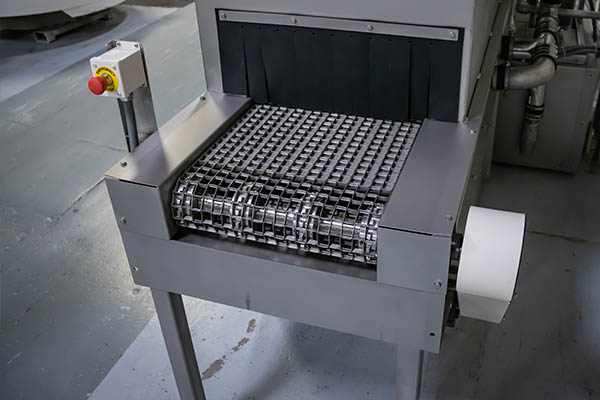
Product Sensors
Photo eyes monitor the load and unload stations for parts and will deactivate the machine if parts stop flowing or to prevent parts falling from the conveyor.
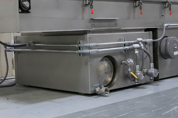
Heated Tanks
Heat your wash tanks up to 140 degrees (F) with an electric tank heater. ALMCO also has optional insulation to cut down on energy costs.
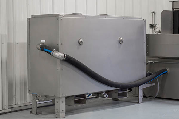
Oil Skimming and Wastewater Treatment
For applications involving cleaning oil-based residue off parts, ALMCO offers an oil skimming solution.
PRWB Conveyor Washer Model Comparison
| Specification | PWRB-1248E | PWRB-1848E | PWRB-2448E |
|---|---|---|---|
| Overall Machine Dimensions (Approximate) | 12′-6″ Long x 68″ Wide x 52″ High | 12′-6″ Long x 74″ Wide x 52″ High | 12′-6″ Long x 82″ Wide x 52″ High |
| Process Stages | Wash: 48″ Drain Area: 18″ Blow-Off: 48″ Unload Station: 18″ |
Wash: 48″ Drain Area: 18″ Blow-Off: 48″ Unload Station: 18″ |
Wash: 48″ Drain Area: 18″ Blow-Off: 48″ Unload Station: 18″ |
| Conveyor Belt Height | 36″ | 36″ | 36″ |
| Work Opening Size | 12″ Wide x 12″ High | 18″ Wide x 12″ High | 24″ Wide x 9″ High |
| Conveyor Motor | 15 HP TEFC, 1750 RPM | 15 HP TEFC, 1750 RPM | 15 HP TEFC, 1750 RPM |
| Solution Tank Capacity | 290 gallons | 290 gallons | 290 gallons |
| Wash Pump | Gusher brand vertical end-suction centrifugal unit | Gusher brand vertical end-suction centrifugal unit | Gusher brand vertical end-suction centrifugal unit |
| Pump Motor | 3 HP, 3450 RPM | 3 HP, 3450 RPM | 5 HP, 3450 RPM |
| Flowrate | 72 GPM @ 40 PSI | 72 GPM @ 40 PSI | 72 GPM @ 40 PSI |
| Power Requirement | 460v (Others Available) 3 Phase, 60 Cycle | 460v (Others Available) 3 Phase, 60 Cycle | 460v (Others Available) 3 Phase, 60 Cycle |
| Drive Unit | AC Variable Frequency | AC Variable Frequency | AC Variable Frequency |
| Blow-Off Unit | 10 HP Gast brand regenerative blower | 10 HP Gast brand regenerative blower | 10 HP Gast brand regenerative blower |
| Blow-Off Rate | 250 CFM @ 100″ WC static pressure | 250 CFM @ 100″ WC static pressure | 250 CFM @ 100″ WC static pressure |
| Operator Controls | 110 volts supplied by a transformer within the control box | 110 volts supplied by a transformer within the control box | 110 volts supplied by a transformer within the control box |
| Electrical Controls | Conformance to N.E.C. electrical specifications | Conformance to N.E.C. electrical specifications | Conformance to N.E.C. electrical specifications |
| Electrical Enclosure | NEMA type 12 panel enclosure mounted on the machine | NEMA type 12 panel enclosure mounted on the machine | NEMA type 12 panel enclosure mounted on the machine |
| Paint | Two coats of Diamond Vogel brand industrial enamel in Lunar White with Midnight Blue accent | Two coats of Diamond Vogel brand industrial enamel in Lunar White with Midnight Blue accent | Two coats of Diamond Vogel brand industrial enamel in Lunar White with Midnight Blue accent |
REQUEST A QUOTE
Let’s talk about the right equipment for your operation.
Tell us about your parts and process. Our team will follow up to discuss the equipment and your application.