
The ALMCO V-23198 TF is the largest standard thru-feed vibratory finishing system in the TF Series, engineered for high-volume, continuous deburring, edge radiusing, cleaning, and surface refinement of production components. With 68 cubic feet of working capacity and process times ranging from 5 to 10 minutes, the V-23198 TF delivers exceptional throughput while maintaining consistent finishing results in demanding manufacturing environments.
Vibratory Finishing Equipment
V-23198 TF Thru-Feed Vibratory Finishing System
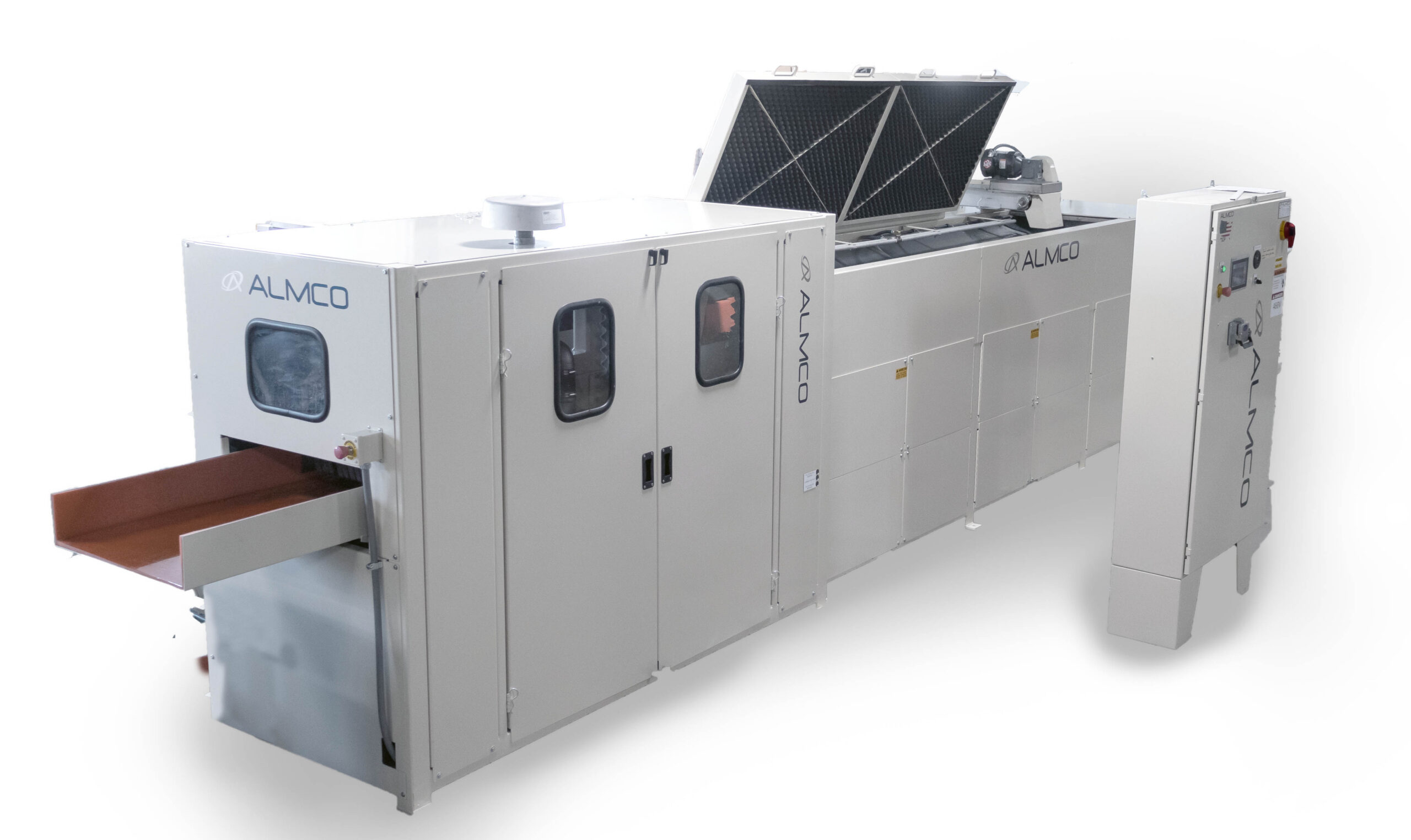
*Shown with additional sound reducing options
OVERVIEW
V-23198 TF Overview
The V-23198 TF is designed for manufacturers requiring continuous processing of large quantities of parts without the interruptions associated with traditional batch finishing systems. Utilizing an extended vibratory process tub measuring 198 inches long, the system continuously conveys parts through the finishing media while maintaining predictable dwell times and consistent part-to-part processing.
As components travel through the machine, controlled vibratory motion generates continuous contact between the media and workpiece surfaces. This action effectively removes burrs, blends sharp edges, refines surfaces, and prepares parts for downstream operations such as coating, assembly, inspection, or packaging.
With a 68 cubic foot working capacity and the ability to process parts up to 19 inches in diameter, the V-23198 TF is ideally suited for demanding production applications where throughput, consistency, and labor efficiency are critical. The extended process path provides dwell times of up to 10 minutes, allowing manufacturers to achieve aggressive deburring and surface refinement while maintaining continuous material flow.
The V-23198 TF is particularly valuable in automated manufacturing environments where uninterrupted processing and predictable production rates are required. Its heavy-duty construction, large media capacity, and powerful vibratory drive system make it an excellent choice for high-volume industrial finishing operations.
KEY ADVANTAGES
- Largest standard thru-feed system in the TF Series
- 68 ft³ working capacity for maximum throughput
- Extended 198″ process length for increased dwell time
- Continuous feed-through operation eliminates batch processing interruptions
- Handles parts up to 19″ in diameter
- Consistent and repeatable finishing results
- Reduces manual handling and labor requirements
COMMON APPLICATIONS
- Edge radiusing stamped parts
- Surface refinement of fabricated components
- Cleaning and burnishing production parts
- Finishing aerospace hardware
- Processing automotive components
- High-volume continuous production finishing
TECHNICAL SPECIFICATIONS
| Overall Machine Dimensions (Approximate) | 23’ Long x 5.5’ Wide x 9.5’ High |
|---|---|
| Processing Tub Dimensions | 116” Long x 19” Wide x 24” Deep |
| Tub Working Capacity | 27 Cubic Feet |
| Tub Lining | 1” Thick, 90 Durometer Polyurethane |
| Main Motor | 15 HP TEFC, 1750 RPM |
| Power Requirement | 460v (Others Available) 3 Phase, 60 Cycle |
| Drive Unit | AC Variable Frequency |
| Vibration Frequency | 875 to 1900 RPM |
| Number of Vibratory Mechanisms | Three (3) |
| Operator Controls | 110 volts supplied by a transformer within the control box |
| Electrical Controls | Conformance to N.E.C. electrical specifications |
| Electrical Enclosure | NEMA type 12 panel enclosure mounted on the machine |
| Paint | Two coats of Diamond Vogel brand industrial enamel in Lunar White with Midnight Blue accent |
SYSTEM DETAILS
- Heavy Duty Framework
- The Vibratory Tub
- How it works - Vibratory Shafts
- Automated Rinse System
- Parts and Media Separator
- Media Return Conveyor
- Electrical Controls
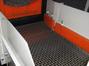
Heavy gauge steel used for structural and support components.
Heavy Duty Framework
The structural frame of the machine is made of heavy structural steel tubing of all welded construction. This framework is shrouded with heavy gauge sheet steel to provide operator protection of all moving parts as well as to provide ease in maintenance, machine cleanliness and appearance. The structural frame supports all components and operating units of the machine and provides a compact machine of unified design.
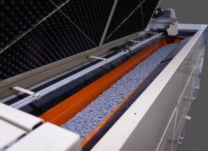
The Thru-Feed vibratory tub
The Vibratory Tub
The vibratory tub of the machine has a cross section with a “U” shaped in design and is fabricated throughout using heavy 3/8″ rolled steel plate of continuous welded construction. The vibratory tub is fully stress relieved after welding to normalize it and to eliminate the possibility of fatigue failure. The tub is designed for ease of removal from the stationary frame. This makes relining and maintenance operations easier.
How it works – Vibratory Shafts
The vibratory action of the tub is accomplished by multiple in-line unbalanced eccentric shafts supported in enclosed housings by special heavy duty vibratory type anti-friction roller bearings freely rotating from other machine components. These bearings are mounted in precision machined housings. Adjustable counterweights provide changes of vibratory amplitude.
The vibratory shafts are driven from the output of the drive unit through a heavy duty automotive type universal joint complete with adaptors for engaging the vibratory shaft and the output shaft of the drive unit. This U-joint is specifically designed to absorb any parallel misalignment between the vibratory shaft. The U-joint is designed for removal without the dismantling of any other machine components.
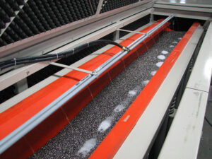
The Thru-Feed Compound dosing system.
Automated Rinse System
The machine is also equipped with a water spray system designed to inject water into the vibratory tub to keep the finishing media clean and free cutting by flushing fines and other contaminants off both parts and media through perforated (replaceable) molded drain plates in the bottom of the tub.
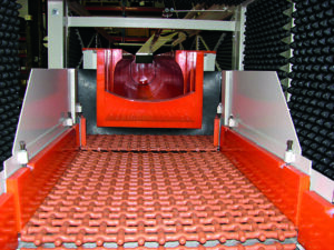
Thru-Feed Media Separator Screen Deck
Parts and Media Separator
A combination parts and media conveyor and separator consisting of a double deck, 22″ wide pan or tray conveying unit operating on an oscillation or vibratory frequency. The top deck of the unit is equipped with a woven wire screen section and designed to receive both parts and media from the discharge chute of the machine and to separate the parts from the media by the media falling through the top screen deck. Both parts and media are conveyed to the discharge end of the separation unit by an oscillation motion where the parts are discharged to your pan or conveyor and the media is discharged to the return media conveyor.
The separator is driven by a 2 HP, TEFC, 1800 RPM ball bearing motor driving an adjustable mechanism through heavy section V-belt and pulleys. All moving parts revolve in heavy duty ball bearings with zerk type grease fittings.
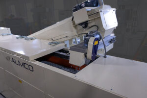
The Thru Feed Media Return Conveyor
Media Return Conveyor
The Media Return Conveyor is designed to receive the separated finishing media from the oscillating conveyor and to move and elevate the media for discharge into the vibratory tub at the loading end.
The media return conveyor has an 18″ wide neoprene coated top surface belt carried by 6″ diameter crown face pulleys. The bottom pulley is an open-finned pulley to prevent any errant media from damaging the belt.
The belt rides on a series of triple roller assemblies, a horizontal center roller with two angle-side rollers to form a trough to carry the media. The rollers, top and bottom pulleys are all adjustable to provide accurate tracking of the belt and the unit is equipped with take-ups for proper belt tensioning. The conveyor is equipped with a nylon bristle brush wiper to remove any carryover media from the belt.
The head shaft of the conveyor turns in anti-friction roller bearings and is driven by a 1-1/2 HP gear motor equipped with a brake for positive holding when not running.
The framework of the conveyor consists of heavy gauge rectangular tubing all-welded into a rigid frame. The sides have removable cover plates for safety, adjustment and maintenance.
The bottom of the conveyor is equipped with a large drawer type pan to catch any fines on the bottom end of the conveyor and for ease of cleanout.
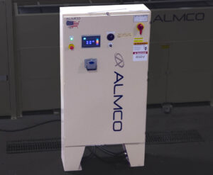
The Electrical Panel on the Thru-Feed Vibratory System.
Electrical Controls
The electrical controls on the machine are in conformance to N.E.C. electrical specifications with the motor operating on 460 volts and all operator controls on 110 volts supplied by a transformer within the control box. All necessary controls for the system’s operation are housed in one NEMA type 12 panel enclosure mounted on the machine.
FREQUENTLY ASKED QUESTIONS
Will vibration from the vibratory tub transfer into the ground and affect other equipment?
The tub is supported in the stationary framework of the machine on heavy coil wound springs mounted on specially designed molded neoprene supports that serve to remove nearly all vibratory motion from the stationary frame of the machine.
How Do Continuous Flow Tubs Work?
Continuous flow or discharge of parts and media from the vibratory tub is accomplished with the use of an inclined chute at the unloading end of the unit. This chute is lined and designed to control the flow rate of the parts and media from the tub as well as to channel them to the deck of the oscillating screen separator.
How do I calculate the correct tub size?
Part Length: The length of your longest part plus at least 4 to 6 inches of clearance on each side determines the minimum tub length.
Working Volume: Total volume is misleading. Look for the “working capacity,” which accounts for the mandatory 1:3 to 1:5 ratio of parts to abrasive media. Overloading slows cycles and ruins parts.
What electrical and plumbing infrastructure do I need?
ALMCO Industrial vibratory tubs usually require 3-phase power. Confirm your shop floor can support the voltage before purchasing. Wet finishing requires a constant influx of water and compound. You must have a floor drain or a dedicated wastewater treatment system. Most environmental laws prohibit dumping compound effluent directly into municipal sewers.
How often does the lining of the tub need to be replaced?
ALMCO uses the highest standard when it comes to tub lining. With a thickness of one inch and 90 durometer polyurethane, the tub lining should last several years depending on the abrasive level of the media and the amount of run time on the system.
Does it come with sound-dampening features?
The sound level is highly dependent on the type of tumbling media and the parts running in the tub. ALMCO offers an integrated acoustic sound lid to help dampen the noise. Some customers choose to build an insulated room around the tub to further eliminate sound.
What is the total cost of ownership (TCO)?
ALMCO Representatives can help you calculate the working costs of running a continuous vibratory system. These costs include
- Media replacement: Budget for the reality that media breaks down and must be continually replenished.
- Compound usage: Factor in the recurring cost of finishing chemicals.
- Replacement parts: ALMCO stocks replacement springs, drains, and motor bearings locally to avoid extended downtime.
- Electricity: Depending on the voltage the amp draw of running continuously will determine your power costs.
How are cycle times controlled in Thru-Feed Vibratory Tub systems?
ALMCO Engineers will use different gates and weights to adjust the speed at which your raw parts flow through the tub. Typically the parts make it through cycling in the vibratory tub in a few minutes. Various parameters like RPM, the counterweight balance on the shafts and the width of the discharge chute play a role in how many parts flow out of the tub.
What are Thru-Feed tubs best used for?
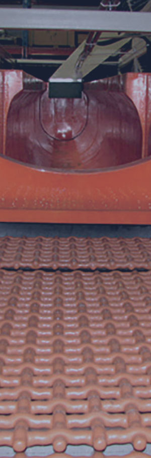
Thru-Feed vibratory tub systems are great for parts that need light deburring or cleaning prior to other processes. Because it only takes the parts a few minutes to make it through the media, there isn’t a long process time to work with. High-volume die casting High-speed stamping presses, Automated screw machine shops, Forging operations where parts exit a furnace or press at a constant interval. Common parts ran in continuous vibratory tubs include stampings, castings, aluminum housings or heat treated components.
Thru-Feed Model Comparison
| Specification | V-16120 TF | V-19158 TF | V-23198 TF |
|---|---|---|---|
| Total Capacity | 27 Cubic Feet | 48 Cubic Feet | 80 Cubic Feet |
| Working Capacity | 24 Cubic Feet | 42 Cubic Feet | 68 Cubic Feet |
| Floor Space | 23′ Long × 5.5′ Wide × 9.5′ High | 36′ Long × 5.5′ Wide × 9.5′ High | 40′ Long × 5.5′ Wide × 9.5′ High |
| Internal Tub Dimensions | 120″ Long × 16″ Wide × 24″ Deep | 158″ Long × 19″ Wide × 28″ Deep | 198″ Long × 23″ Wide × 30″ Deep |
| Estimated Process Time | 3-5 Minutes | 4-8 Minutes | 5-10 Minutes |
| Power Consumption | 50 Amps | 70 Amps | 90 Amps |
| Ceramic Media Required | 2,500 lbs. | 4,500 lbs. | 7,200 lbs. |
| Steel Media Required | 8,100 lbs. | 14,400 lbs. | 24,000 lbs. |
| Plastic Media Required | 1,800 lbs. | 3,120 lbs. | 5,200 lbs. |
| Maximum Part Size | 12″ Diameter | 15″ Diameter | 19″ Diameter |
REQUEST A QUOTE
Let’s talk about the right equipment for your operation.
Tell us about your parts and process. Our team will follow up to discuss the equipment and your application.